Renewal of the Bridge Structures at the Darmstädter Kreuz
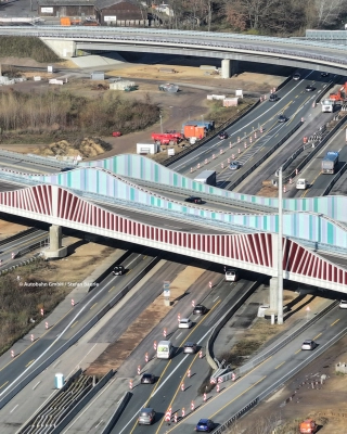
One of Germany’s most important traffic axes, the interchange between the A5 and A67 near Darmstadt (between Mannheim and Frankfurt), was due for renewal. The four existing bridges displayed load‑bearing deficiencies and have since been completely demolished and replaced by four new bridge structures, including additional traffic lanes. The new bridges are designed with architectural appeal. In order to install the new bridges over the road with as little disruption as possible, a sliding‑in system was chosen.
The firm Eiffage Infra Süd‑West (a subsidiary of Eiffage) is the main contractor for the re‑engineering of this traffic artery. The Belgian company Iemants, also part of Eiffage, carried out the fabrication and installation of the new steel bridges. The engineering consultancy Iv contributed to the design.
The main bridge comprises two adjacent, virtually identical bridges and is also referred to as the „Zentralbauwerk“. The basic design of these bridges was provided by the client. Iemants reviewed the associated sliding‑in concept and developed it fully to guarantee that the loads during installation remained below the permissible values.
The new bridge is very slender by design, resulting in the force‐introduction into the web plates from the temporary supports being critical. The methodology had to be revised to achieve better force introduction. Iemants therefore devised a new design for the sliding shoes and implemented it. This enabled a controlled and manageable execution. Iv provided design support for the development of the sliding‑in system, which consists of a drive system with cables and a support system with sliding shoes. Iv also carried out the structural verification of the bridge during the various stages of installation.
The transformation of the interchange is large scale. The works are well advanced and are currently in the finishing phase. The existing complex of four bridges has already been completely demolished and replaced, with the addition of extra lanes. The works are being carried out while traffic is flowing, and take place in different sections, namely:
Nordrampe : The northern ramp, which carries the A67 with two lanes and four spans from south to north over the A5, was built in 1966 and had a total length of 138 metres. With a remaining service life ending December 2019, the condition of this structure was the most critical. The bridge was replaced by a 170‑metre long steel structure with three box girders.
Südrampe: The southern ramp had a length of 138 metres and likewise four spans, dating from 1967. The new southern ramp is shortened to 94 metres and also contains three steel box girders.
Zentralbauwerk: The new Zentralbauwerk consists of two steel‑concrete composite bridges lying side by side. The transverse beams are provided with dowels onto which at a later stage a concrete deck was cast. The main girders are built from continuously varying plate girders, with the maximum height of the cross‑section being 7 metres.
The large steel bridge components were transported from Iemants’ production facility in Balen (Belgium) by water to Mannheim, and then by road to Darmstadt. The assembly of the components took place on a pre‑construction site aligned with the bridge. This process made it possible to slide each bridge into its final position, thereby minimising disruption to motorway traffic.
The two bridges were each built in five phases:
Phase A: The first half of the bridge was assembled on the pre‑construction site. The end cross‑girder of the first bridge segment was connected to a fixed point on the abutment.
Phase B: After completion of the first bridge segment, a cable was connected between the fixed point and the end cross‑girder of the first segment. In preparation for the first pull‑in process the strands were tensioned.
Phase C: The first bridge segment was slid to its temporary position. A temporary connection was then made between the pier and the bridge.
Phase D: The second part of the bridge was placed and connected to the first part. A cable was again connected to the end cross‑girder and the fixed point. The cable was then re‑tensioned.
Phase E: The bridge was slid into its final position.
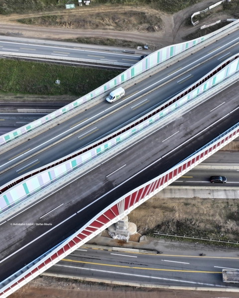
The new bridge complex meets the highest German standards and is characterised by a modern appearance with striking colour accents. The interior of the Zentralbauwerk is equipped with strips in various colours, from green to purple, which adds a unique aspect to the bridge.
The start of construction of the Südrampe took place in March 2021, followed by the Nordrampe in the same year and the Zentralbauwerk in 2023. The final hand‑over has already occurred.
A single bridge consists of two large continuous plate girders spanning multiple supports. The height of the plate girders follows the bending moment distribution. Between the main girders transverse beams are placed, onto which dowels are mounted. A cast concrete deck is poured over the transverse beams, resulting in a steel‑concrete composite deck. A single bridge is approximately 16 metres wide and has a length of about 160 metres, with a main span of 72 metres and two side spans of 38 metres.
One of the biggest challenges of the project was the shifting of the bridges. For this purpose, bespoke sliding shoes with bearings, load‑spreading plates and a sliding surface of polished stainless steel and polytetrafluoroethylene (PTFE) were developed. This system ensures balanced and predictable friction and movement. The company Trelleborg, in cooperation with Iemants, developed special rubber blocks which are incorporated into the sliding shoes. These blocks enable a flexible support that guarantees the correct load distribution.
Iv provided support for the detailed development of the sliding‑in system, which consists of a drive system with cables and a support system with sliding shoes. Additionally, Iv carried out the structural verification of the bridge during the various mounting steps. Based on this, adjustments and optimisations were performed.
The bridge is pulled from the pre‑construction site with the help of cables and a launching frame over specially developed sliding shoes. Because an existing motorway had to be crossed, finding sufficient temporary supports and space was a challenge. Although each bridge ultimately has three main spans, extra intermediate supports were used in the main spans for the sliding process. By intelligently utilising the abutments and already taking this into account in the design, sufficient space was found to absorb the launching and support‑point forces.
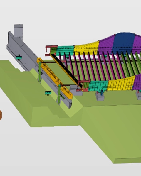
The pull cables have a fixed anchor at the abutment and a launched frame was developed here. At the transverse beams at the rear of the bridge a jack construction is incorporated which can pull on the cable. This effectively pulls the bridge over the road. The bridge crosses the motorway at an angle and has a skew connection at the abutments. Here a comparatively large end cross‑girder is provided.
During sliding the bridge has a different span and also cantilevers. Therefore the bridge deck deflects at the front. A temporary “nose” is mounted at the front of the bridge. This nose can absorb this deflection and lifts the bridge onto the next bearing.
Because the bridge deforms and undergoes vertical angular distortion when passing the temporary supports, the sliding shoes were developed so that they are elastically supported and can hinge, thereby following the curvature of the bridge.
The bridge is also equipped with jacks near the sliding shoes. These allow the bridge to be lifted and inspections and, if necessary, repairs to the sliding surfaces can be carried out.
Just like an ice‑sledge, the bridge can also slide sideways during movement. To prevent this, lateral supports are installed, which also include a jack facility to press the bridge into the correct position.
At the permanent supports the bearings have been widened locally and the bridge is also locally wider. The lateral supports must be able to pass this widening. For this purpose they are partially demountable. The sliding surfaces of the lateral supports can hinge so that the bridge is not jammed by a small horizontal angular distortion.
The sliding shoes performed so well during installation that the installation proceeded quickly, without problems and without notable wear. The principle will be used more frequently by Iemants.
Although the execution appears simple, it required considerable creativity and technical ingenuity to carefully calculate the many mounting steps and to ensure at each stage the safety and controllability of the project. The good cooperation among the various parties was crucial. The constructive and practical attitude of all involved contributed to the successful execution of this complex project.
Jaco, managing director Consult, would be delighted to discuss this with you! Get in touch via +31 88 943 3100 or send a message.
