Making level crossings safer: the critical design aspects
Many level crossings in the Netherlands are vulnerable to low-loader trailers, which means that there is a risk that a low-loader could get stuck when driving over such a crossing. The low height of low-loaders increases the risk of them getting stuck at a level crossing because the crossing is raised. Life-threatening situations can occur when a low-loader becomes stuck or blocks a level crossing.
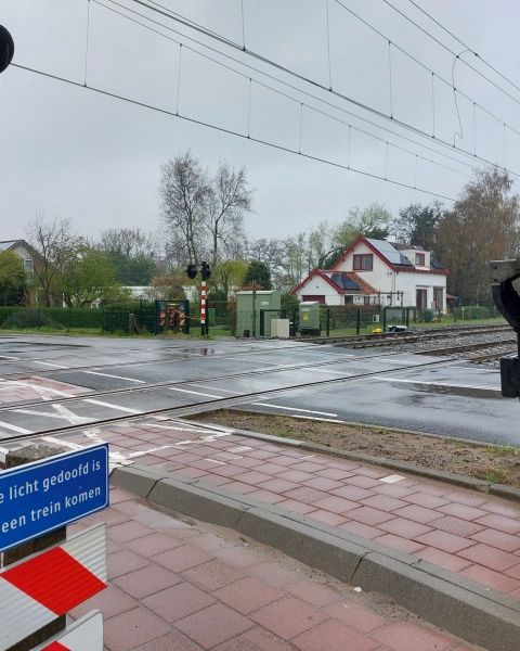
Such level crossings are included in publicly accessible databases, such as the RDW digital road map and the ProRail low-loader booklet. These databases are essential for hauliers to rule out the possibility of the vehicle getting stuck in advance. The basic principle for crossing a level crossing is that it must be done within 15 seconds. If it is expected to take longer, ProRail must be contacted. One of these level crossings is located on Stationsweg in Lisse. Agricultural vehicles cross over this level crossing and, in the current situation, make contact with the raised surface of the crossing.
Iv was commissioned by ProRail to provide a concept design for various alternative road and/or rail axes to eliminate the low-loader vulnerability. The level crossing at Stationsweg is a crossing with two curved rails. The canting of the rails results in an unfavourable longitudinal profile of the road as both lie on the same level, creating an upward ‘slope’ for road traffic at the level crossing. At the highest peak of the slope, agricultural traffic makes contact with the road and, therefore, risks getting stuck.
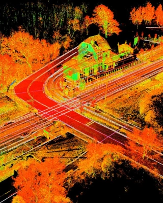
To find the best option, measuring the exact position of the road and rail is essential. This is done using 3D laser scanning combined with tachymetry and GNSS (Global Navigation Satellite System). With 3D laser scanning, a separate scan is made at multiple locations. For each scan, the environment and multiple targets are measured. This is also performed with a tachymeter to allow the individual 3D scans to be aligned (registered) with very high accuracy (± 3 mm). The result of this registration is a complete 3D point cloud of the environment. In addition, GNSS is used to measure distinctive points visible in the 3D scan, allowing the 3D point cloud to be determined in RD coordinates.
The advantage of 3D laser scanning in the above method is that objects in the area are measured contactless in a relatively short time with a remarkably high point density without having to touch the rails. Therefore, there is no need to request an interruption to train services. The 3D point cloud forms the basis for further processing, from which designs can be created.
To determine whether a level crossing is vulnerable to low-loader trailers, the so-called hazard class k is calculated. The calculation assumes an axis distance of a. Based on the road and rail measurements; the intersection/arrow d (in the vertical direction) will be determined.
The hazard class is derived from the formula k = a/d.
At level crossings with k ≤ 100 there may be a risk of grounding. Experience shows no issues with a peak curve of more than 200 metres. Following measurements, the design phase aims to achieve a k value greater than 100.
There are several options for developing the designs. Low-loader vulnerability can be eliminated by adapting the rails, the road or both. If the rail is adjusted, it may turn out that the curve radius needs to be increased. This reduces the canting and leads to smaller height differences.
An alternative is to create a more gradual road course towards the incline at the level crossing. A hybrid solution is also an option. In this case, for example, the rails can be lowered, creating space in the road profile to make the approach to the level crossing more gradual.
When developing the designs, all possible interfaces must also be taken into account. In the case of the level crossing at Lisse, the presence of cables and pipes, the water management and maintaining the safety of the level crossing had to be considered. For example, at the Stationsweg level crossing, recurring problems were found with the rail position: so-called blind deflection (clappers). Blind deflection occurs when there is a gap between the bottom of the sleeper and the ballast bed when the rail is unloaded. When the rail is loaded, deflection will be observed. More extreme forms of blind deflection are referred to as clappers.
There are several reasons for the occurrence of blind deflection. It is suspected that the reoccurrence of clappers at these locations is due to the soil saturation with rainwater. Given this suspicion, the design must not create a situation that leads to poorer water management. Additionally, extra measures can always be taken with regard to water management.
As far as cables and pipes are concerned, these will always need to be inventoried in the first instance by way of a KLIC report so that any limitations can be taken into account. Depending on the results, any interfaces that limit the options for adapting the road and/or rail must be considered when developing the concepts. We also examine any negative consequences for level crossing safety in the new situation. If any are identified as unavoidable, we will propose additional measures.
In short, various aspects of level crossing safety need to be accounted for in the design phase. In the coming period, Iv will start to map the situation at the level crossing in Lisse to arrive at a weighted recommendation in which an improvement in level crossing safety can be achieved based on the criteria of impact on road traffic, impact on rail traffic, cost and impact on the environment.
Wouter, managing director Infra and also COO of Iv, would be delighted to discuss this with you! Get in touch via +31 88 943 3200 or send a message.
